Calculate a flat statically indeterminate rod system. Calculation of statically indeterminate systems by the force method
Statically indeterminate systems are rod systems in which equilibrium equations alone are not sufficient to determine the reactions of supports. From a kinematic point of view, these are rod systems whose number of degrees of freedom is less than the number of connections. To reveal the static indetermination of such systems, it is necessary to construct additional equations for the compatibility of deformations. The number of such equations is determined by the static indetermination number of the rod system. Figure 8.14 shows examples of statically indeterminate beams and frames.
The beam shown in Fig. 8.14b is called continuous beam. This name comes from the fact that the intermediate support only supports the beam. At the point of support, the beam is not cut by the hinge, the hinge is not cut into the body of the beam. Therefore, the influence of stresses and deformations that the beam experiences on the left span also affects the right span. If at the place of the intermediate support we cut a hinge into the body of the beam, then as a result the system will become statically determinate - from one beam we will get two beams independent of each other, each of which will be statically determinate. It should be noted that continuous beams are less material-intensive than split beams, since they more rationally distribute bending moments along their length. In this regard, continuous beams are widely used in construction and mechanical engineering. However, continuous beams, being statically indeterminate, require a special calculation technique, which includes the use of system deformations.
Before starting to calculate statically indeterminate systems, it is necessary to learn how to determine the degree of their static indetermination. One of the simplest rules for determining the degree of static indetermination is the following:
 ,
(8.3)
,
(8.3)
Where  number of connections imposed on the structure;
  the number of possible independent equilibrium equations that can be compiled for the system under consideration.
Let us use equation (8.3) to determine the degree of static indetermination of the systems depicted in Fig. 8.14.
The beam shown in Fig. 8.14a is once statically indeterminate, since it has three connections on the left support and one connection on the right support. Only three independent equilibrium equations can be constructed for such a beam. Thus, the degree of static indetermination of the beam  . The continuous beam shown in Fig. 8.14b is also once statically indeterminate, since it has two connections on the left support and one connection each on the intermediate support and on the right support - a total of four connections. Thus, the degree of its static indetermination
  .
.
The frame shown in Fig. 8.14c, is three times statically indeterminate, since it has six connections in the supports. Only three independent equilibrium equations can be constructed for this frame. Thus, the degree of static indetermination for this frame from equation (8.3) is equal to:  . The degree of static indetermination of the frame shown in Fig. 8.18d is equal to four, since the frame has seven connections on the supports. Consequently, the degree of its static indetermination is equal to
  .
.

Rule (8.3) for determining the degree of static indetermination is used only for simple systems. In more complex cases this rule does not work. Figure 8.15 shows a frame, the degree of static indetermination of which cannot be determined using equation (8.3).
Externally, the system shown in Figure 8.15 is statically indeterminate five times. This can be easily established using equation (8.3): from six external connections (three in section A, three in section B and two in section C), three possible equilibrium equations are subtracted. However, this system also has internal static indetermination. It is impossible to take into account internal static indetermination using equation (8.3). Before moving on to determining the degree of static indetermination of the frame shown in Fig. 8.15, we introduce several definitions. The first of these definitions includes the concept of a simple hinge.
Simple called a hinge connecting two rods (Fig. 8.16).
Fig.8.16. Simple hinge
A hinge connecting several rods is called complex(Fig.8.17).
Fig.8.17. Complex hinge
The number of simple hinges that can replace one complex hinge is determined from the formula:
 ,
(8.4)
,
(8.4)
Where  - number of rods included in the assembly.
Let us recalculate the complex hinge shown in Fig. 8.17 into the number of simple hinges using formula (8.4):  . Thus, the complex hinge shown in Fig. 8.17 can be replaced with four simple hinges.
Let's introduce one more concept - closed loop.
Let's prove the theorem: any closed contour is three times statically indeterminate.
To prove the theorem, consider a closed loop loaded with external forces (Fig. 8.18).

Let's cut a closed contour with a vertical section and show the internal force factors that arise at the section. Three internal factors arise in each section: shear force  , bending moment
  and longitudinal force
  . In total, on each of the cut off parts of the contour, in addition to external forces, six internal factors act (Fig. 8.18, b, c). Considering the equilibrium of one of the cut-off parts, for example, the left one (Fig. 8.18, b), we find out that the problem is three times statically indeterminate, since for the cut-off part it is possible to construct only three independent equilibrium equations, and there are six unknown forces acting on the cut-off part . Thus, the degree of static indetermination of a closed loop is equal to
  . The theorem has been proven.
Now, using the concept of a simple hinge and a closed loop, we can formulate another rule for determining the degree of static indetermination:
 ,
(8.5)
,
(8.5)
Where  number of closed loops;
  number of hinges in terms of simple ones (8.4).
Using equation (8.5), we determine the degree of static indetermination of the frame shown in Fig. 8.15. The frame has five contours  , including the contour formed by the support rods. The hinge at node D is simple as it connects two rods. The hinge in section K is complex because it connects four rods. The number of simple hinges that could replace the hinge in section K is equal according to formula (8.4):
  . Hinge C is also complex because it connects three rods. For this hinge
  . In addition, the system has two more simple hinges, with which it is attached to the base. Thus, the number of simple hinges in the system is equal to
  . Substituting the number of closed contours
  and the number of simple hinges
  in formula (8.5) we determine the degree of static indetermination of the frame:
  . Thus, shown in Fig. 8.15 frame, seven times statically indeterminate. This means that to calculate such a system, it is necessary to compose, in addition to the three equilibrium equations, seven equations of compatibility of deformations. By solving the thus obtained system of 10 equations for the unknowns included in these equations, it is possible to determine both the magnitude of the reactions in the external connections and the internal forces arising in the frame. The procedure for solving this problem can be somewhat simplified by eliminating the equilibrium equations from the system of equations. However, this approach requires the use of special solution methods, one of which is the method of forces.
Statically indeterminate systems are those systems in which the internal forces cannot be determined only from the equilibrium equations (static equations).
Statically indeterminate constructions have so-called extra communications. They can occur in supports, rods, and other elements. Such connections are called “superfluous” because they are not necessary to ensure the balance of the structure, but are determined by the requirements for its strength and rigidity. Such extra connections are called external. In addition, unnecessary connections may arise due to the peculiarities of the design itself. For example, a closed frame contour (Fig. 46, G) has three unknown internal forces in each section, i.e. there are six in total, and three of them are “extra”. This extra effort is called internal. Based on the number of external or internal “extra” connections, they establish the degree of static indetermination of the system. It is equal to the difference between the number of unknowns to be determined and the number of static equations. With one “extra” unknown, the system is called once, or once statically indeterminate, with two - twice statically indeterminate, etc.
The design shown in Fig. 46, A, is once statically indeterminate, and the structures shown in Fig. 46, b And V, - twice statically indeterminate, in Fig. 46, g - three times with a statically indeterminate structure.
When solving statically indeterminate problems, in addition to static equations, equations are used that take into account the deformations of structural elements.
There are several methods for solving statically indeterminate problems: displacement comparison method, force method, displacement method.
Force method
When calculating statically indeterminate systems, forces are taken as unknowns.
Calculation by force method carried out in the following sequence:
- 1. Establish the degree of static indetermination.
- 2. By removing “extra” connections, replace the original system with a statically definable one, called main system. Several such systems can be built, while observing the condition of their geo
metric immutability.


- 3. The main system is loaded with given external forces and “extra” unknown forces that replace the action of remote connections, resulting in equivalent system.
- 4. To ensure the equivalence of the original and main systems, the unknown forces must be selected so that the deformations of the main system do not differ from the deformations of the original statically indeterminate system. For this movement of application points, “extra” unknowns in the direction of their action are equal to zero. From the additional equations obtained in this way, the values of the “extra” unknown efforts are determined. Determining the displacements of the corresponding points can be done in any way, but it is better to use the most general Mohr method.
- 5. After determining the values of “extra” unknown forces, the reactions are determined and diagrams of internal forces are constructed, sections are selected and strength is checked in the usual way.
Canonical equations of the force method
Additional equations of displacement, expressing the equality to zero of displacement in the directions of “extra” unknowns, are conveniently compiled in the so-called canonical form, those. according to a certain pattern. Let us show this using the example of solving the simplest statically indeterminate system (Fig. 47, A).
Let's choose the console as the main system, discarding the hinge support. We obtain an equivalent system after applying its external force T 7 and the “extra” unknown X(Fig. 47, b).
Canonical equation, expressing the equality of point displacement to zero IN from the forces of F X, will
From the equation we have

For a system that has two “extra” connections, the system of canonical equations has the form:

- 8 11 X 1 + b 12 ^2 + ^1
- 621-^1 + 622^2 "I" ^20-
Movements A[r And b[y, included in the canonical equations, are determined by Mohr's method.
For systems consisting of rectilinear elements, it is convenient to calculate displacements using Vereshchagin’s method.
For example, for the problem shown in Fig. 47, multiplying the diagrams (Fig. 48), we obtain the coefficients of the canonical equation:
1 2 I 3 1 I/I 2 1 5 I1 3
E]b LL =-/ / -/ = -, E]A LR =-------- +-------.
1 11 2 3 3 1 1Р 2 2 2 2 3 2/ 48 E]
We get Hl - - = - E.
Having determined the strength X, we actually found the support reaction I'm in. Next, the problem of determining internal force factors can be solved, as usual, using the section method.
MINISTRY OF EDUCATION OF THE RUSSIAN FEDERATION
GOVERNMENT INSTITUTION
KUZBASS STATE TECHNICAL UNIVERSITY
Department of Strength of Materials
CALCULATION OF STATICALLY INDETERMINATE HINGE-ROD SYSTEMS UNDER TENSION-COMPRESSION
Guidelines for performing calculation and graphic tasks on the strength of materials for students of all specialties
Compiled by: V.D. Moiseenko
Approved at a meeting of the department Minutes No. 8 of June 29, 2001
An electronic copy is located in the library of the main building of the KuzSTU State University
Kemerovo 2002
Introduction. Scope and purpose of the assignment
A statically indeterminate hinge-rod system is one in which the forces in the rods and reactions in the supports cannot be determined only from the equilibrium condition.
Figure 1 shows a conventional bracket consisting of two rods. The forces N 1 and N 2 in the rods of this bracket are easily determined from the equilibrium condition of the system of converging forces applied to the cut out node C, since two equations for this system of forces with two unknowns are solved.
If the design of the bracket is complicated by adding another rod (Fig. 1, b), then the forces in the rods cannot be determined in the same way, since for node C it is still possible to create only two static equilibrium equations (ΣХ = 0; ΣY = 0), and the number of unknown efforts is three. We have a once statically indeterminate system.
By complicating the design and introducing new rods, it is possible to obtain a statically indeterminate system twice (see Fig. 1, c), three times, etc. Consequently, by n times a statically indeterminate system we mean a system in which the number of connections exceeds the number of independent static equations by n units.
The additional equations necessary to solve the problem can be found by considering the system in a deformed state and establishing connections between the displacements and deformations of structural elements. The resulting equations are called deformation compatibility equations.
Figure 2 shows diagrams of some statically indeterminate systems.

Fig.2. Some types of statically indeterminate systems
When studying the section “Statically indeterminate rod systems” and completing this computational and graphic task, the student must learn the features of statically indeterminate systems; gain skills in revealing static indetermination, determining forces in structural elements and selecting cross-sectional areas from strength conditions.
In the assignment, the student must complete the following work:
- determine the forces in the rods and select the cross-sectional areas from the action of external loads;
- determine additional stresses in the rods due to temperature changes;
- determine additional installation stresses caused by inaccurate manufacturing of rods;
- select cross-sections of rods according to the limit state.
The volume and form of performing the calculation and graphic task depend on the volume of the course being studied and are discussed by the teacher during practical classes.
1. Brief theoretical information
When solving statically indeterminate problems, the following order should be followed:
1.1. Consider the static side of the problem. Construct a plan of forces and compose static equations.
1.2. Consider the geometric side of the problem. Build a travel plan. Create additional deformation compatibility equations in such a quantity that all unknown forces can be found.

1.3. Consider the physical side of the problem. According to the laws of physics (in temperature calculations) and according to Hooke’s law, express the deformations in the equations of their compatibility through unknown forces acting in the rods:
∆l t =α ∆t l |
∆l N = |
||||
E.F. |
|||||
1.4. Carry out a joint solution of the equations of statics, geometry, physics and determine the unknown forces.
1.5. Using compressive or tensile strength conditions N/F = [σ], select the cross-sectional areas of the rods.
1.6. With known forces in the rods and accepted cross-sectional areas, calculate the normal stresses using the formula
σ = N F .
2. Example
Given: An absolutely rigid beam AB is supported, as shown in Fig. 3, loaded with a uniformly distributed load and force P.
Fig.3. Diagram of a statically indeterminate system

Initial data for calculation
Material |
[σ ]Р , |
[σ] SJ, |
α , |
F ST |
|||||||||||||
2 105 |
125 10-7 |
||||||||||||||||
1 105 |
165 10-7 |
||||||||||||||||
Required: |
|||||||||||||||||
Determine the forces (N CT; N M), cross-sectional areas (F CT; |
|||||||||||||||||
F M) and stress (σ C r T; σ M r) in steel (ST) and copper (M) rod- |
|||||||||||||||||
nyakh from the action of external loads P and q. |
;σ М t |
||||||||||||||||
Determine additional stresses in the rods (σ ST t |
|||||||||||||||||
from a temperature change by ∆ t = + 20 o C. |
|||||||||||||||||
Determine the additional stresses in the rods caused by |
|||||||||||||||||
inaccuracy in the manufacture of the vertical rod ∆ = 0.1 cm. |
|||||||||||||||||
4. Determine the total stresses in the rods due to loads, temperature changes and manufacturing inaccuracies.
2.1. Calculation of a statically indeterminate hinge-rod system for external loading
P = 30 kN q = 15 kN/m
A C B
Fig.4. Initial calculation scheme

2.1.1. Static side of the problem
The static side of the problem is considered by the force plan. The force plan is a calculation diagram that shows all the forces (both known and unknown) applied to the element of the hinge-rod system whose equilibrium is being considered (in our case, this is the rigid beam AB). Let's cut the steel and copper rods and replace their discarded lower parts with internal forces (Fig. 5).
P = 30 kN q = 15 kN/m
A C B
60°
a =2 m |
||||||||
N st |
||||||||
B = 4 m |
||||||||
Rice. 5. Plan of forces from external loads
From the plan of forces (see Fig. 5) we write down the equations of static equilibrium. To answer the first question of the problem, you need to know the forces in the rods - steel and copper. In this case, there is no need to calculate the reaction of the articulated fixed support. Therefore, out of three
possible static equations (ΣX = 0; ΣY = 0; Σm c = 0) we write
one that does not include the reactions of the articulated-fixed support C:
∑ mC = 0
− N CT a + q a 2 2 + p a + NM sin60o b = 0,
− N ST 2 + 15 2 2 2 + 30 2 − NM 0.866 4 = 0,
After algebraic operations, the equilibrium equation takes the form
NCT + 1.73NM = 45. |

2.1.2. Geometric side of the problem
The geometric side of the problem is considered by the displacement plan. The displacement plan is a calculation diagram that shows the position of the hinge-rod system before and after loading. On the movement plan we indicate the movements of the beam points (AA1 and BB1),
absolute deformations of copper and steel rods (∆ l ST; ∆ l M)
(Fig. 6). Moreover, due to small deformations, we move the beam points vertically up or down, and mark the deformations of the inclined rods with a perpendicular.
60° |
||||||
∆l st |
||||||
∆l m |
||||||
4 m |
||||||
Rice. 6. Plan of displacements due to external loads
Using the displacement plan, we draw up a deformation compatibility equation. First of all, let’s write down the ratio of the displacements of the points of the beam from the similarity of triangles AA1 C and CBB1 (Fig. 6):
We express the displacements of the points of the beam (AA1 and BB1) in terms of deformations
rods (∆ l CT; ∆ l M): |
||||||
AA1 = ∆ l ST |
||||||
From triangle BB1 B2 we express: |
||||||
BB= |
B1 B2 |
∆l M |
||||
sin60o |
sin60o. |
|||||
We substitute expressions (2.3) and (2.4) into relation (2.2):
∆ lCT sin 60o |
|||
∆l M |
|||
∆ lCT 0.866 |
||||||||
∆l M |
||||||||
0.866 ∆ lST = |
0.5∆ lМ. |
|||||||
This is the equation |
||||||||
deformation compatibility. |
||||||||
2.1.3. Physical side of the problem
The resulting deformation compatibility equation (2.5) in this form cannot be solved with the equilibrium equation (2.1), because the unknown quantities included in them are of different nature.
The absolute deformations ∆ l CT and ∆ l M in equation (2.5) can be expressed
through forces in the rods according to Hooke's law: |
∆l = |
|||||||||||||
N ST l ST |
||||||||||||||
NM lМ |
||||||||||||||
E ST F ST |
E M F M |
|||||||||||||
Let us substitute the numerical values of the initial data, and F ST we express |
||||||||||||||
through F M according to the initial data: |
||||||||||||||
F ST |
||||||||||||||
4, from where F ST = 4 F M = 0.75F M, |
||||||||||||||
NST 1,2 |
NM 1.9 |
|||||||||||||
and we get |
||||||||||||||
105 0.75 F |
1 105 F |
|||||||||||||
After performing arithmetic operations we get: |
||||||||||||||
0.67NCT = 0.95NM. |
||||||||||||||
We obtained an equation for the compatibility of deformations, written in terms of the forces in the rods.
2.1.4. Synthesis
Let us solve the equilibrium equation (2.1) and the deformation compatibility equation (2.6) together.
NCT + 1.73NM = 45
0.67NST = 0.95NМ.
From the second equation of the system we express the force N ST:
N ST + |
NM = 1.42NM |
|
and substitute it into the first equation of the system.
1.42 NM +1.73 NM = 45 |
3.15 NM = 45, |
|||||
N M = |
14.3 kN, then |
NST = 1.42 14.3 = 20.3 kN. |
||||
The positive result of N ST and N M confirms our assumptions of compression of the steel rod and tension of the copper rod, which means that the forces in the rods will be:
NST = –20.3 kN; |
NM = 14.3 kN. |
2.1.5. Selection of cross sections of rods
The selection of cross sections of rods is carried out according to the conditions of tensile strength - compression:
N F ≤ [σ] .
a) The cross-sectional area of the steel rod required from the strength condition will be determined:
N ST |
≥ 1,7 10− 4 |
||||||||||||||
[ σ ST ] compress |
|||||||||||||||
F ST |
|||||||||||||||
Moreover, according to the given area ratio |
|||||||||||||||
4 area |
|||||||||||||||
copper rod should be equal to: |
|||||||||||||||
4 1,7 10− 4 |
2,27 10− 4 |
||||||||||||||
b) The cross-sectional area of the copper rod required from the strength condition will be determined:
≥ 1,7 10 |
− 4 m 2 |
|||||
[σ M] dis. |
84 103 |
|||||
In this case, according to the given area ratio, the area of the steel rod should be equal to:
FST = 4 3 FM = 4 3 1.7 10− 4 = 1.275 10− 4 m2 ..
We accept large cross-sectional areas of rods:
FST = 1.7 10− 4 m2; |
FM = 2.27 10− 4 m2. |
Given the accepted cross-sectional areas of the copper and steel rods, we determine the stresses in these rods.
N ST |
− 20.3 10− 3 MN |
= − 119.4 MPa, |
||||||
1.7 10− 4 m2 |
||||||||
F ST |
||||||||
p N M |
14.3 10− 3 MN |
63 MPa. |
||||||
σМ = |
2.27 10− 4 m2 |
|||||||
2.2. Temperature calculation of a statically indeterminate hinge-rod system
The purpose of temperature calculation is to determine additional stresses in copper and steel rods due to temperature changes.
Let's say the system heats up by ∆ t = 20 o C. The solution algorithm remains the same. The initial design diagram is shown in Fig. 7.
Rod systems, support reactions and internal force factors in which cannot be found from equilibrium equations alone are called statically indeterminate.
The difference between the number of unknown unknown forces and independent equilibrium equations determines degree of static indetermination of the system. The degree of static indetermination is always equal to the number of redundant (superfluous) connections, the removal of which turns a statically indeterminate system into a statically definable geometrically unchangeable system. Both external (support) connections and internal ones can be redundant, imposing certain restrictions on the movement of system sections relative to each other.
Geometrically unchangeable is a system whose shape can only be changed due to deformations of its elements.
Geometrically variable is a system whose elements can move under the influence of external forces without deformation (mechanism).
Shown in Fig. 12.1 the frame has seven external (support) links. To determine the forces in these connections (support reactions), you can create only three independent equilibrium equations. Consequently, this system has four redundant connections, which means that it is statically indeterminate four times. Thus, the degree of static indetermination for flat frames is equal to:
Where R- number of support reactions.
A contour consisting of a number of elements (straight or curved), rigidly (without hinges) connected to each other and forming a closed circuit is called closed . The rectangular frame shown in Figure 12.2 is a closed loop. It is three times statically indeterminate, since to transform it into statically definable it is necessary to cut one of its elements and eliminate three extra connections. The reactions of these connections are: longitudinal force, transverse force and bending moment acting at the cut site; they cannot be determined using static equations. Under similar conditions, in the sense of static indetermination, there is any closed contour that is always three times statically indeterminate.
Including a hinge in a frame assembly in which two rods meet, or placing it anywhere on the axis of the rod, removes one connection and reduces the overall degree of static indetermination by one. Such a hinge is called single or simple (Fig. 12.3).


In general, each hinge included in a node connecting c rods, reduces the degree of static uncertainty by c-1 , since such a hinge replaces c-1 single hinges (Fig. 12.3). Thus, the degree of static indetermination of the system in the presence of closed contours is determined by the formula.
Statically indeterminate is a system that cannot be calculated using static equations alone, since it has unnecessary connections. To calculate such systems, additional equations are compiled that take into account the deformations of the system.
Statically indeterminate systems have a number of characteristic features:
1. Statically indeterminate structures are more rigid than the corresponding ones statically definable, since they have additional connections.
2. B statically indeterminate systems have less internal forces, which determines their efficiency compared to statically definable
systems under identical external loads.
3. Breaking unnecessary connections in statically indeterminate system does not always lead to destruction, while loss of communication in statically definable system makes it geometrically variable.
4. For calculation statically indeterminate systems must first be specified by the geometric characteristics of the cross sections of the elements, i.e. in fact, their shape and size, since their change leads to a change in the forces in the connections and a new distribution of forces in all elements of the system.
5. When calculating statically indeterminate systems, it is necessary to select the construction material in advance, since it is necessary to know its elastic moduli.
6. B statically indeterminate systems, temperature effects, settlement of supports, inaccuracies in manufacturing and installation cause additional forces.
Main calculation methodsstatically indeterminate systems are:
1. Force method.
Here, efforts—forces and moments—are considered as unknowns.
2.Movement method. Unknown are the deformation factors - rotation angles and linear displacements.
3.Mixed method. Here, part of the unknowns represents effort, and the other part represents displacement.
4. Combined method. Used when calculating symmetrical systems for asymmetrical loads. It turns out that it is advisable to calculate the system for the symmetrical component of a given load using the displacement method, and for the inversely symmetrical component using the force method.
In addition to the above analytical methods, various numerical methods are used when calculating particularly complex systems.
Canonical equations of the force method
To obtain additional equations discussed in the previous paragraph, you must first transform the given n times statically indeterminate system into a statically determinate one by removing unnecessary connections from it. The resulting statically definable system is called basic. Note that transforming a given system into a statically determinable one is not necessary. Sometimes a modification of the force method is used, in which the main system can be statically indeterminate, however, the presentation of this issue is beyond the scope of this manual. Elimination of any connections does not change the internal forces and deformations of the system if additional forces and moments are applied to it, which are reactions of the discarded connections. This means that if a given load and reactions of remote connections are applied to the main system, then the main and given systems will become equivalent.
In a given system, there can be no movements in the directions of the existing rigid connections, including those connections that were discarded during the transition to the main system, therefore, in the main system, movements in the directions of the discarded connections must be equal to zero. And for this, the reactions of discarded bonds must have strictly defined values.
The condition for zero displacement in the direction of any i-th connection out of n discarded on the basis of the principle of independence of the action of forces has the form:
where the first index means the direction of movement and the number of the discarded connection, and the second indicates the reason that caused the movement, i.e. is the movement in the direction of the i-th bond caused by the reaction of the k-th bond; - movement in the direction of the i-th connection caused by the simultaneous action of the entire external load.
In the force method, the reaction of the kth bond is usually denoted by Xk. Taking into account this designation and due to the validity of Hooke’s law, displacements can be represented as:
where is a unit (or specific) movement in the direction of the i-th bond caused by the reaction i.e. a reaction coinciding in direction with Xk, but equal to unity.
Substituting (2) into (1), we get:
Physical meaning equation (3): the movement in the main system in the direction of the i-th discarded connection is zero.
Writing expressions similar to (3) for the entire set of discarded connections, we obtain system of canonical equationsforce method:
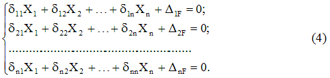
The form of equation (4), i.e. the number of terms in each of them and their total number is determined only by the degree of static indetermination of the system and does not depend on its specific features.
The coefficients of the system of canonical equations (4) are determined by the Mohr-Vereshchagin method by multiplying the corresponding diagrams. All these coefficients, as stated above, represent displacements; the coefficients associated with the unknowns are unit displacements, and the free terms are freight. Unit movements are divided into main ones, located along the main diagonal and having the same indices and side(). The main movements are always positive, unlike the secondary ones. Symmetrically located displacements in accordance with the theorem of reciprocity of displacements are equal to each other, i.e. .
Calculation algorithm using the force method
Regardless of the features of the design under consideration, we can distinguish the following sequence of calculations for statically indeterminate systems force method:
1. Define degree of static indetermination.
2. Select the main system.
3. Form an equivalent system.
4. Record the system canonical equations.
5. Construct unit and load diagrams of internal force factors arising in the elements of the structure under consideration.
6. Calculate the coefficients of the unknowns and the free terms of the system of canonical equations.
7. Construct a total unit diagram.
8. Perform a universal check of coefficients for unknown and free terms.
9. Solve system (4), i.e. determine the reactions of extra connections.
10. Construct diagrams of emerging internal force factors for a given system (in other words, final diagrams).
11. Perform static and kinematic checks.
Note that points 7, 8, 11 of the above algorithm are not absolutely necessary, although they allow you to control the correctness of the calculation. And for systems with one extra connection, points 7 and 8 are simply meaningless, since in this case the total unit diagram coincides with the unit one.
Let us dwell in more detail on some of the above calculation stages.
Choosing a Primary System
This is the most important stage of the calculation, since the rational choice of the main system significantly simplifies the computational work. Let's consider possible ways to remove unnecessary connections, which determines the type of the main system.
1. Removal of unnecessary connections is carried out by completely removing some supports or replacing them with supports with fewer connections. Reactions acting in the directions of discarded bonds are extra unknowns. Figure 1, b, c, d shows various versions of the equivalent system obtained by this method for the frame (Figure 1, a).
2. The placement of hinges in intermediate sections of the rods makes it possible to establish a connection corresponding to the bending moment in each such section. These moments are unnecessary unknowns. For a frame with a degree of static indetermination n=3 (Fig. 2, a), when choosing the main system, it is necessary to install three hinges. The position of these hinges can be arbitrary, but satisfy the requirement of geometric immutability of the system (Fig. 2, b).
3. Cutting the rod eliminates three connections corresponding to the internal forces M, Q, N (Fig. 2, c). In particular cases (Fig. 2, d), cutting a rod along the hinge releases two connections (Fig. 2, e), and cutting a straight rod with hinges at the ends releases one connection (Fig. 2, f).
Among the connections of a statically indeterminate system, a distinction is made between absolutely necessary and conditionally necessary. Absolutely necessary connections include those connections that, when removed, make the system geometrically variable. An absolutely necessary connection is characterized by static determinability of the effort in it, i.e. the reaction of such a bond can be calculated from the equilibrium condition. When choosing the main system, absolutely necessary connections cannot be discarded.

Connections, when removed, the system continues to remain geometrically unchanged, are called conditionally necessary. The system from which such a connection has been removed may be the primary system force method.
Calculation of coefficients and free terms of canonical equations
This stage of calculation is preceded by the construction of unit and load diagrams of internal force factors (for beams and frames - diagrams of bending moments). Unit diagrams are constructed from the action of a dimensionless unit force or a dimensionless unit moment, coinciding in direction with the direction of the corresponding extra unknown in the equivalent system, and are denoted by , and a unit diagram by .
The load diagram is constructed from an external load applied to the main system. In this case, you can build one diagram from the simultaneous action of all external loads or several diagrams, separately from each of the applied loads. Such a division of one load diagram into several simpler ones is, as a rule, advisable only when among the acting loads there is a uniformly distributed one, and the diagram of moments in the corresponding section under it is alternating in sign. In this case, in each canonical equation the number of free terms will be equal to the number of constructed load diagrams.
Unit and load displacements (coefficients and free terms of the canonical equations) in the general case can be calculated by Mohr's method. For beams and frames this can be done using Vereshchagin's rule.
Universal verification of coefficients and free terms of canonical equations
To perform a universal check, it is necessary to construct a total unit diagram - a diagram of the moments from the simultaneous action of all unit forces applied to the main system:
![]()
Let's multiply the total unit diagram with the diagram:
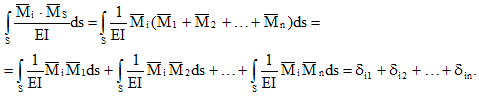
Thus, the result of multiplying the total and i-th unit diagrams is a movement in the direction of the i-th connection from the joint action of individual extra unknowns. This displacement is equal to the sum of the coefficients of the i-th canonical equation:
![]()
This check is called line by line and is satisfied for each canonical equation.
Instead of n line-by-line checks, one is most often performed - universal verification, which consists of multiplying the total unit diagram by itself and checking the condition:
If the universal check is performed, then the unit movements are calculated correctly; if not, it is necessary to perform line-by-line checks, which will make it possible to clarify the movement in the calculation of which an error was made.
To check cargo movements, it is necessary to multiply the total unit and load diagrams of bending moments:
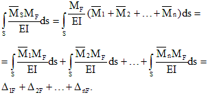
Thus, checking the free terms of the system of canonical equations (4) consists in fulfilling the condition.


